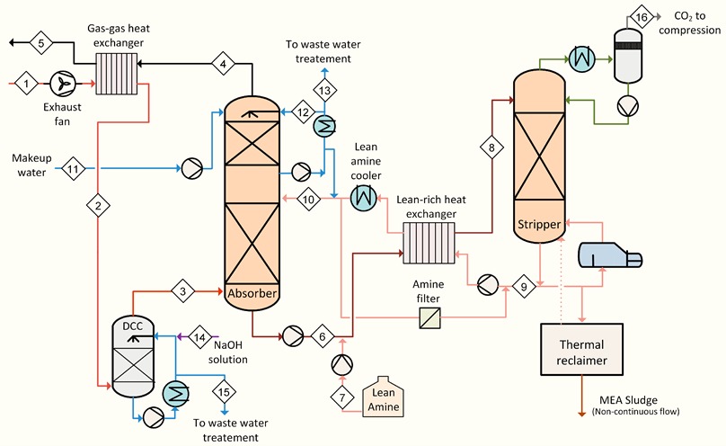
Post-Combustion CO2 Capture (PCC), carbon dioxide is separated from the flue gas of a conventional plant, after fuels have completely burned. Thus, the CO2 needs to be separated from a mixture of mainly N2, H2O, O2, and other minor constituents like NOx and SOx.
While the process scheme remains largely the same of the traditional sour gas treatments, major
differences in operating conditions require modifications in design and process requirements:
Volumetric flow rates:
The large low-pressure volumetric flow rate of flue gas requires larger equipment, and consequently higher investment costs per amount of CO2 separated from the feed gas.CO2 partial pressure:
The low partial pressure of CO2 in flue gas leads to a higher energy requirement for the separation process.Oxygen content:
The presence of oxygen and sour components (SOx and NOx) in the feed gas causes chemical attack on organic capture agents, such as amines.Emissions:
Gas treated in a PCC process is directly emitted to the atmosphere, which imposes environmental constraints on its composition.Notably, PCC systems are generally simple add-on facilities, whose installation do not require major retrofitting works in the existing plant. Tie-ins to the existing plant and integration with existing facilities are limited to the following areas
- Integration with the flue gas path
- Interfacing with the plant combustion control system
- Provision of utilities (Steam, Cooling Water, Demi Water, Instrument Air, Nitrogen, Electricity)
The required modifications can be executed using standard engineering methods.
The flue gas is fed at the bottom of the absorption column, after being cooled down to improve the
absorption performances. Upstream the absorber, a blower is generally required to overcome the
additional pressure losses in the flue gas path. As the flue gas rises in the column, the CO2 is
absorbed by the chemical solvent in aqueous solution in counter-current flow. The column is filled with random or structured packing to increase the contact area between gas and liquid phase. A washing section at the top of the absorber reduces the carryover of solvent to the environment by contacting the gas with cold water.
The treated flue gas is released to the atmosphere at the top of the absorber, while the CO2-rich
solution is gathered and pumped from the bottom to the regenerator, passing through a rich-lean heat exchanger where it is pre-heated.
In the regenerator the CO2-rich solution flows downwards: CO2 is stripped off from the rich solution and is separated at the top of the column. The stripping vapor is generated in the reboiler which functions as a combined condenser-evaporator: low-pressure steam is condensed at one side,
transferring its latent heat to the solution on the other side.
The CO2-rich gas stream from the top of the Regenerator is cooled-down in the overhead condenser
where part of the water vapor is condensed and separated from the gas stream in the KO Drum. The water is sent to the Regenerator by dedicated pumps as reflux of the column.
The separated CO2 gas stream can be dehydrated and compressed up to the required pressure level
and sent to the battery limits of the unit for the specific utilization. Low pressure steam reboiler is utilized to supply the required heat for the amine regeneration.
The CO2-lean solution from the bottom absorber is cooled-down in the -lean-rich heat exchanger; final cooling is realized in the trim cooler to achieve the desired temperature level for the optimal operation of the absorber.

